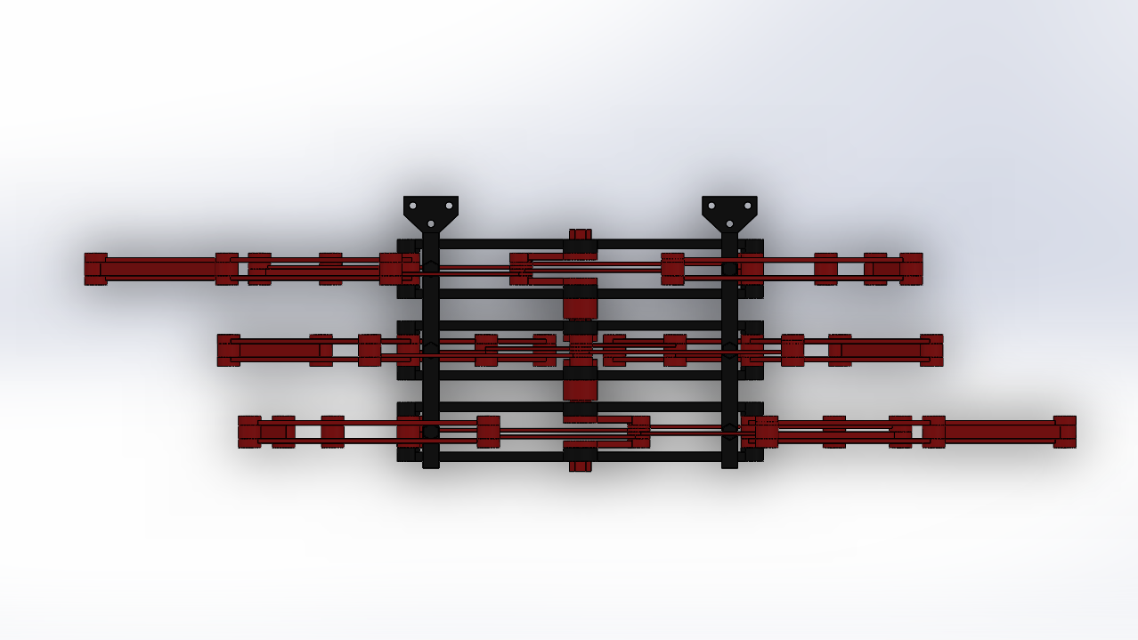
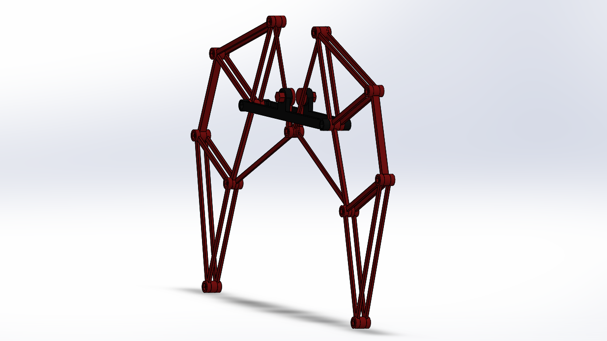
I've seen some Jansen's Linkage machines use two sections of legs with the cranks 180 degrees apart, but I wanted to go all out. Using three sets of legs should result in a slightly smoother walk cycle versus the two set solution. Three sets of legs are mated together and their cranks are coupled with 120 degree offsets.
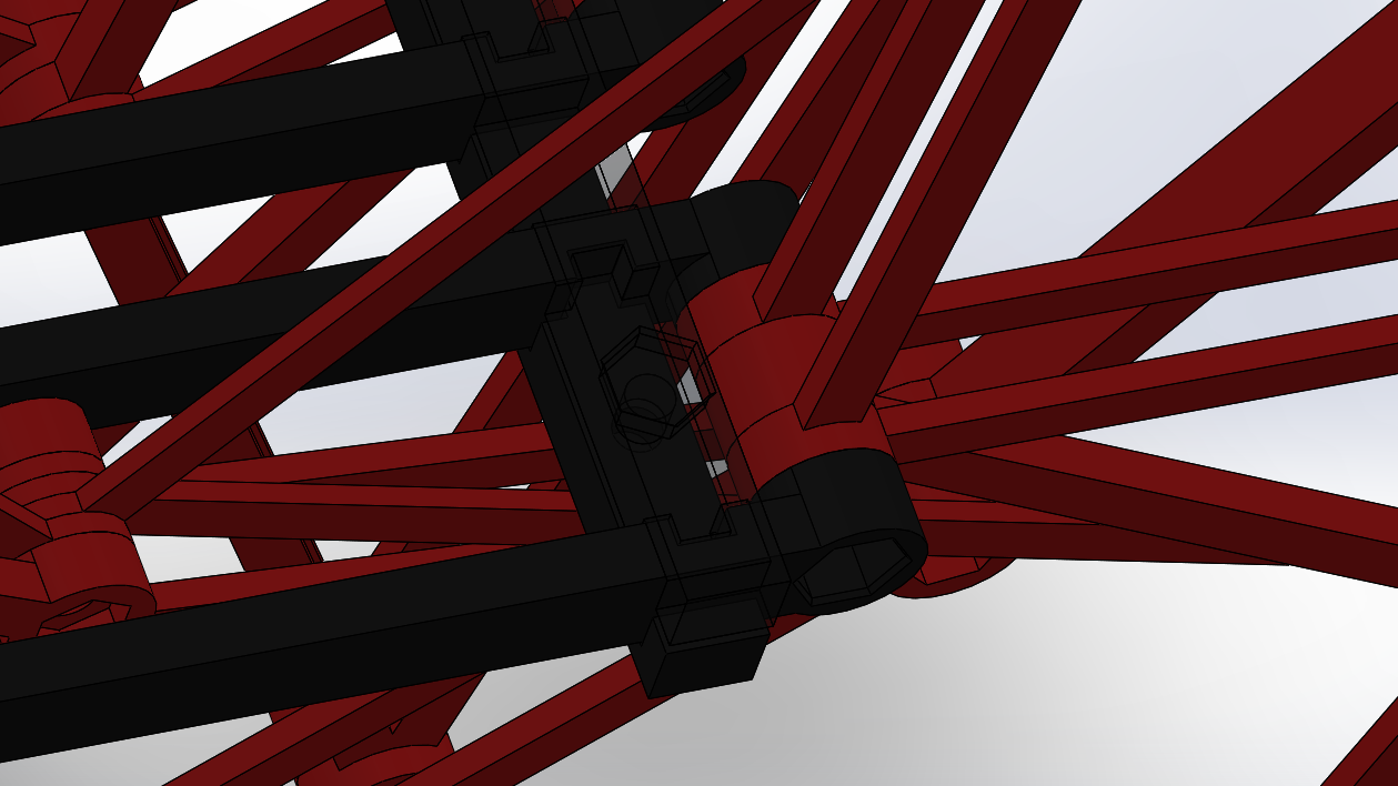
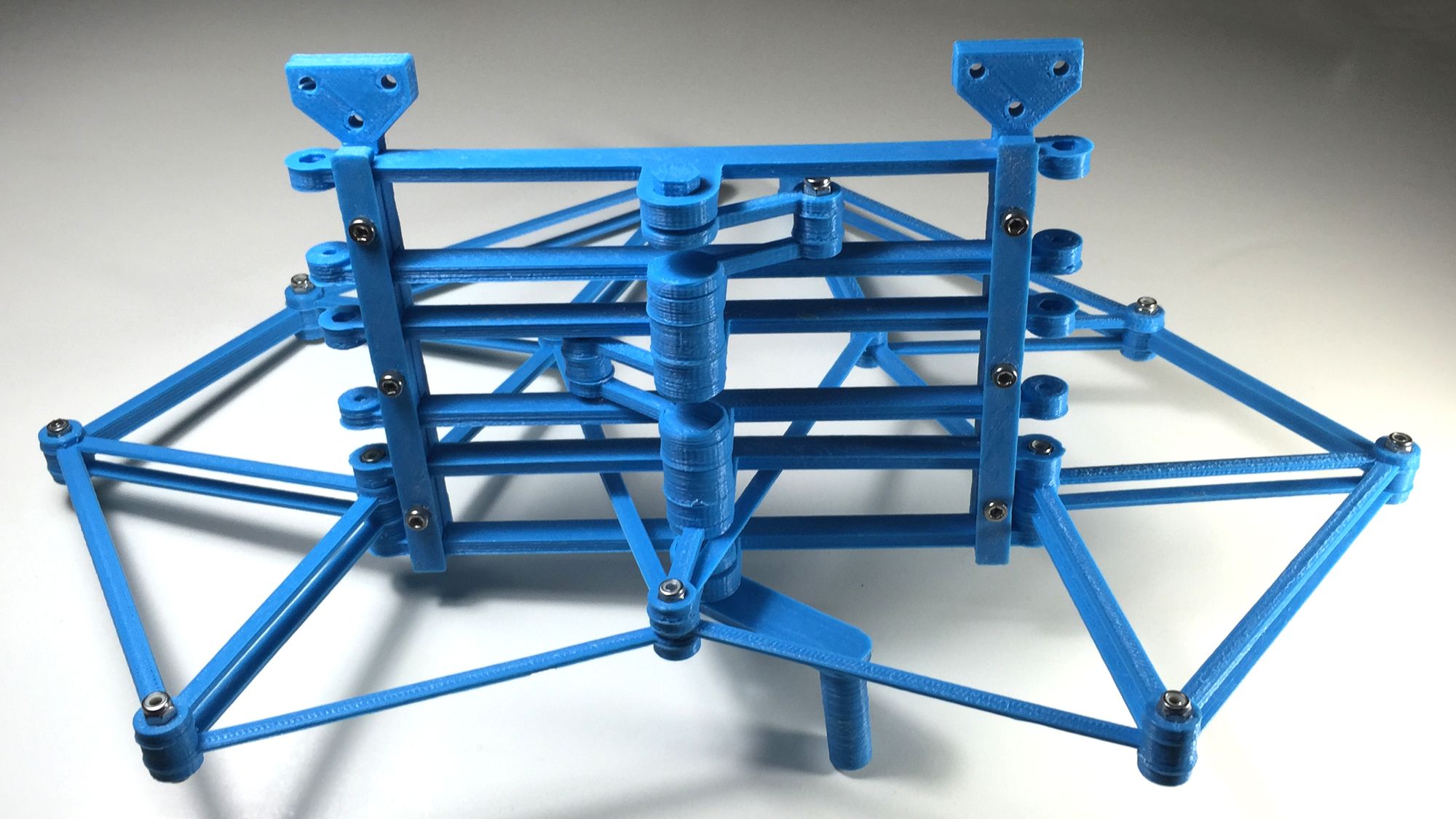
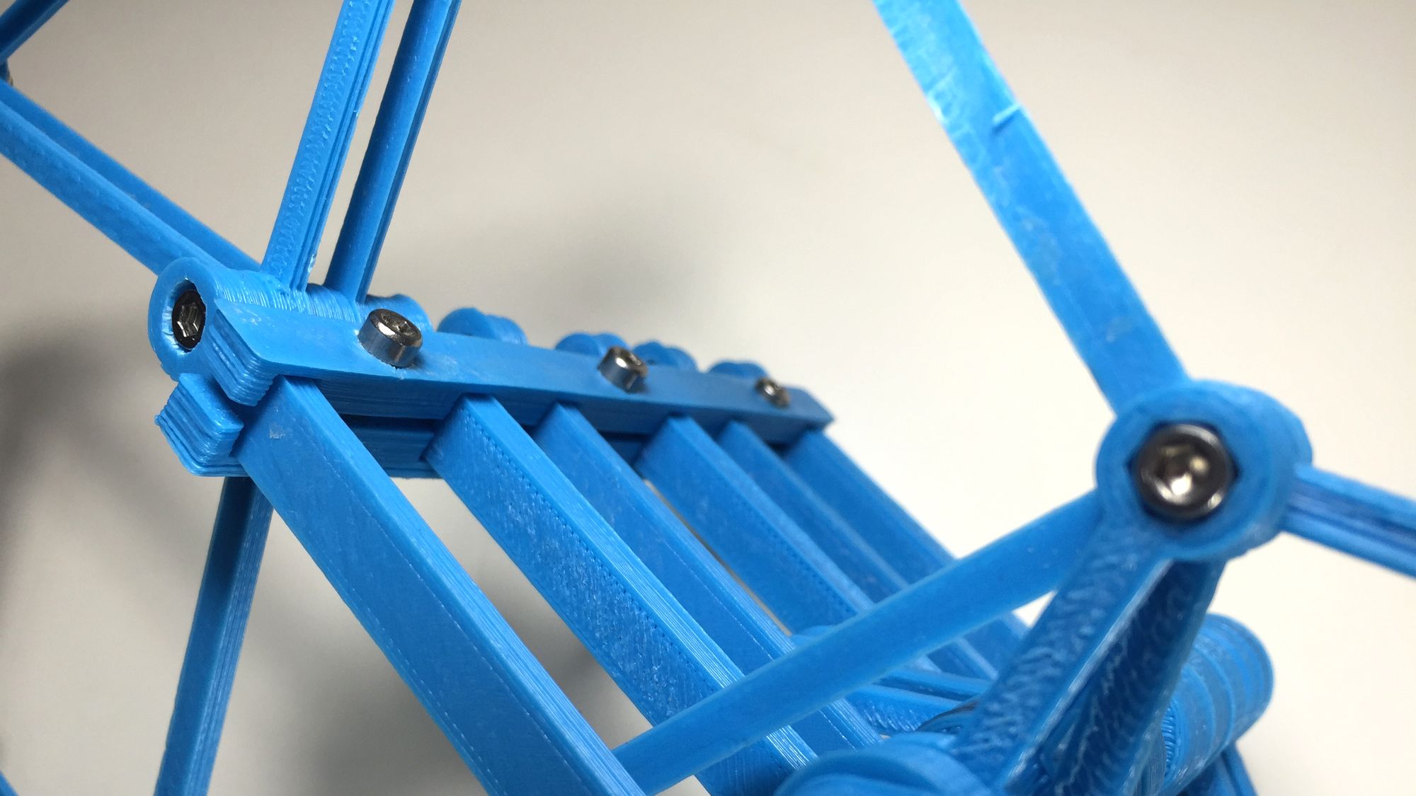
The legs sections are linked together via keyed clamping assembly. Each leg section's main frame has a notched area that mates perfectly with the coupling beams. Due to my printers inaccuracies, the tolerance on the parts were set to ensure a proper fit when assembled. In the image below, the top coupling beam has been made translucent.
The lateral couplers are designed to accommodate three leg sections, but could easily be expanded to support many more.
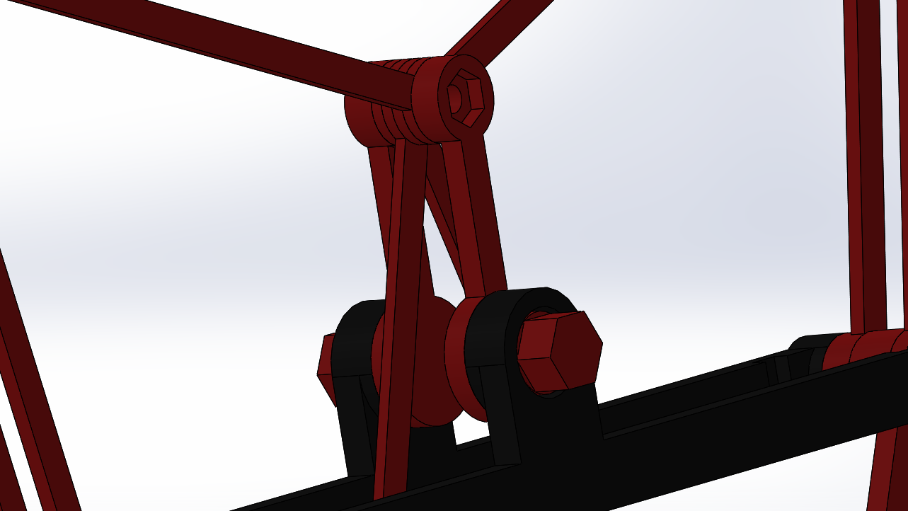
The crank couplers were also sized to produce a snap fit when assembled. The hexagon shape make it very easy to offset each leg section 120 degrees.
The Leg Assembly are linked to a main chassis via these extended tabs with mounting holes. Since the legs are more or less symmetrical, the same design can be use for both sides of the machine.
To ensure sizing and tolerances were correct a mockup was printed and assembled. Only one of the leg sections were made to same time and material. In there place, are specially designed spacers that have the same depth as the drive linkages in the actual leg. I also made a little hand crank to test it out.
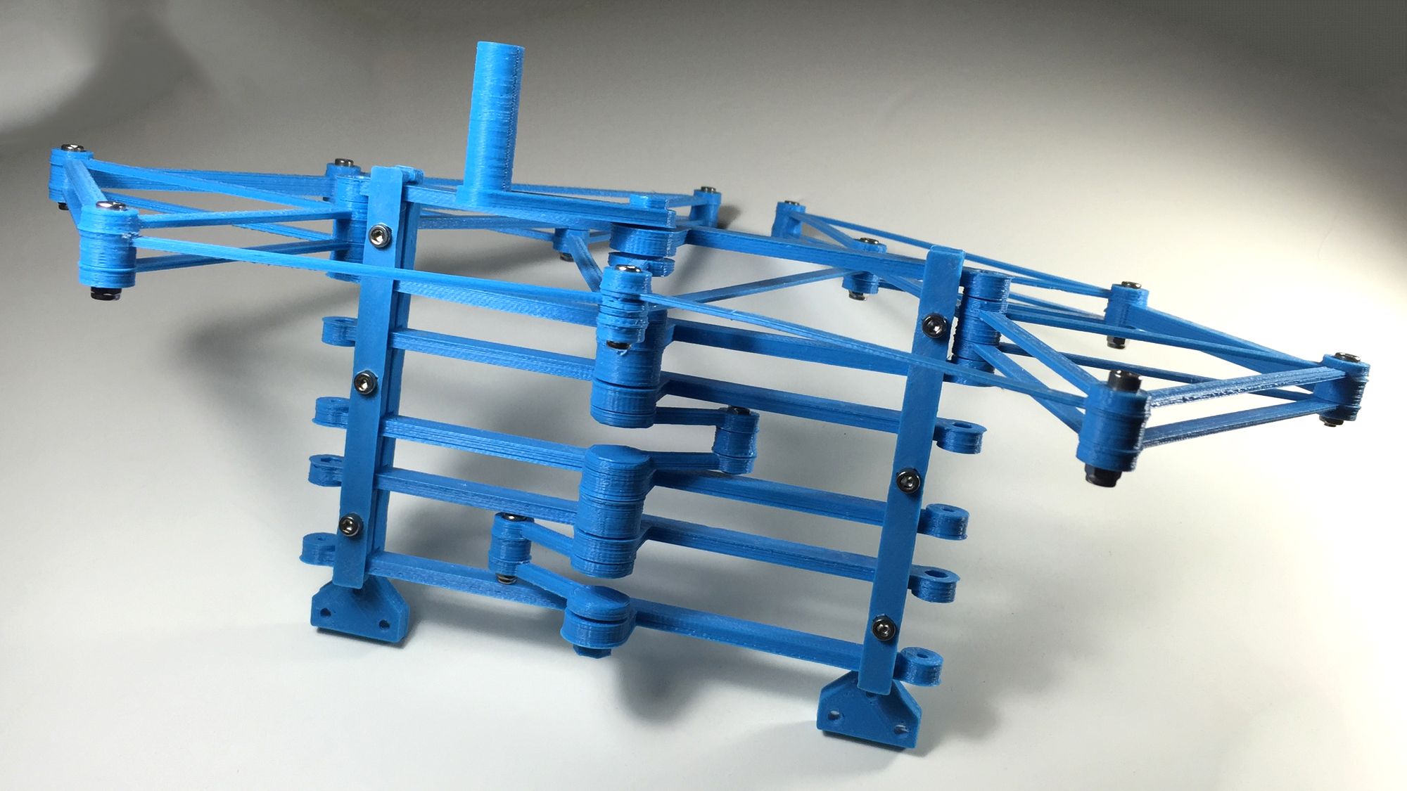

The design validated nicely. The next step is the chassis.