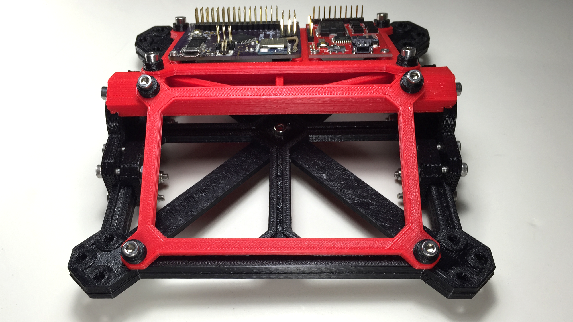
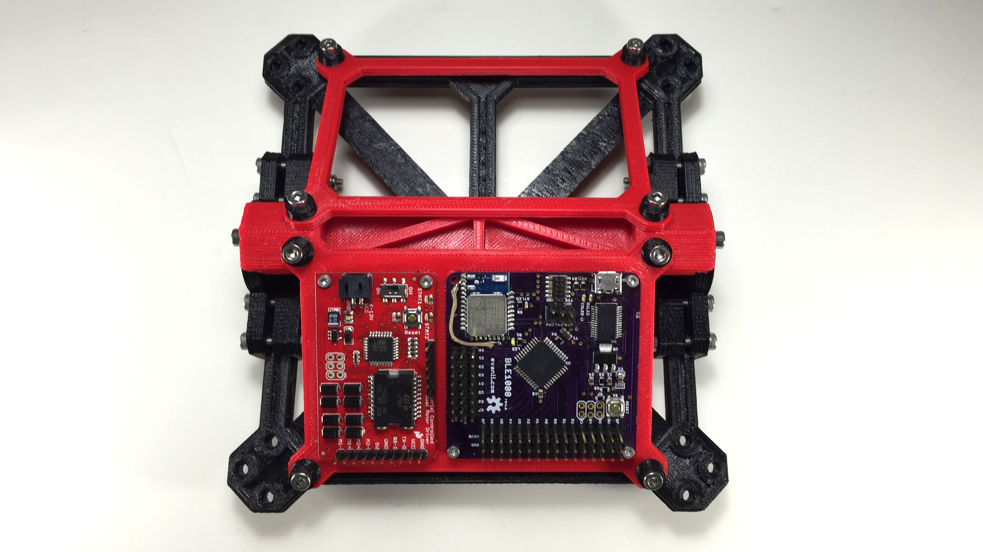
The assembly that brings it all together. The chassis had to hold the electronic, batteries, and motors, as well as, accepting the two legs assemblies. In the electronics department, I would be using a serial motor driver from Sparkfun, and my custom BLE1000 Bluetooth Low Energy board. I haven't selected a battery yet, but I have various NiCad and LiPo batteries laying around that would do the job. Finally, the motors are some gear motors from Sparkfun as well. They are no longer on sale, but you can find the specs here.
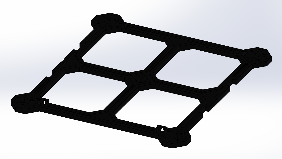
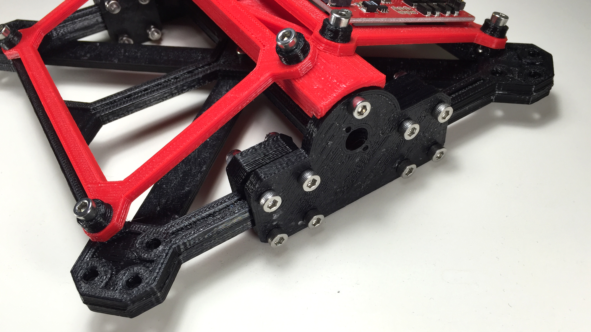
The chassis is composed of several components put together to produce a strong and stiff structure. The top layer of the chassis has notches on each side to accommodate the motor mount plates and slots where nuts would be permanently glued in place as mounting points for the support plates.
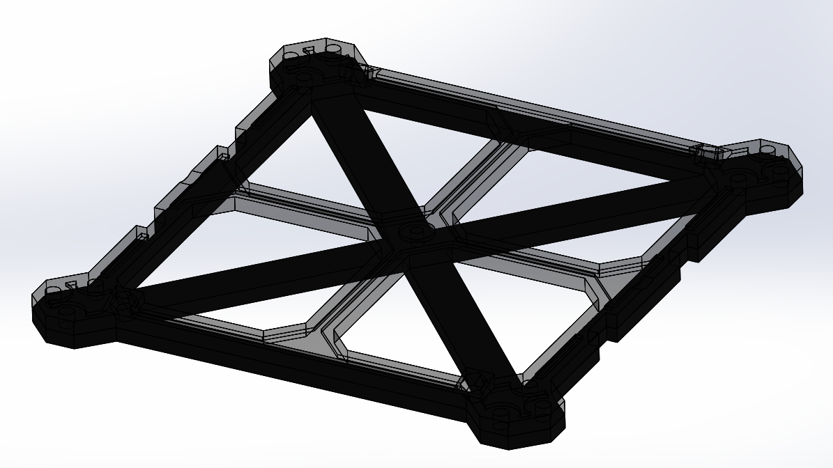
The primary purpose of the lower layer of the chassis is to add stiffness to the structure and to give the motor mounting plates more area to clamp too. The leg assembly mounting holes pass through both layers for improved load transfer.
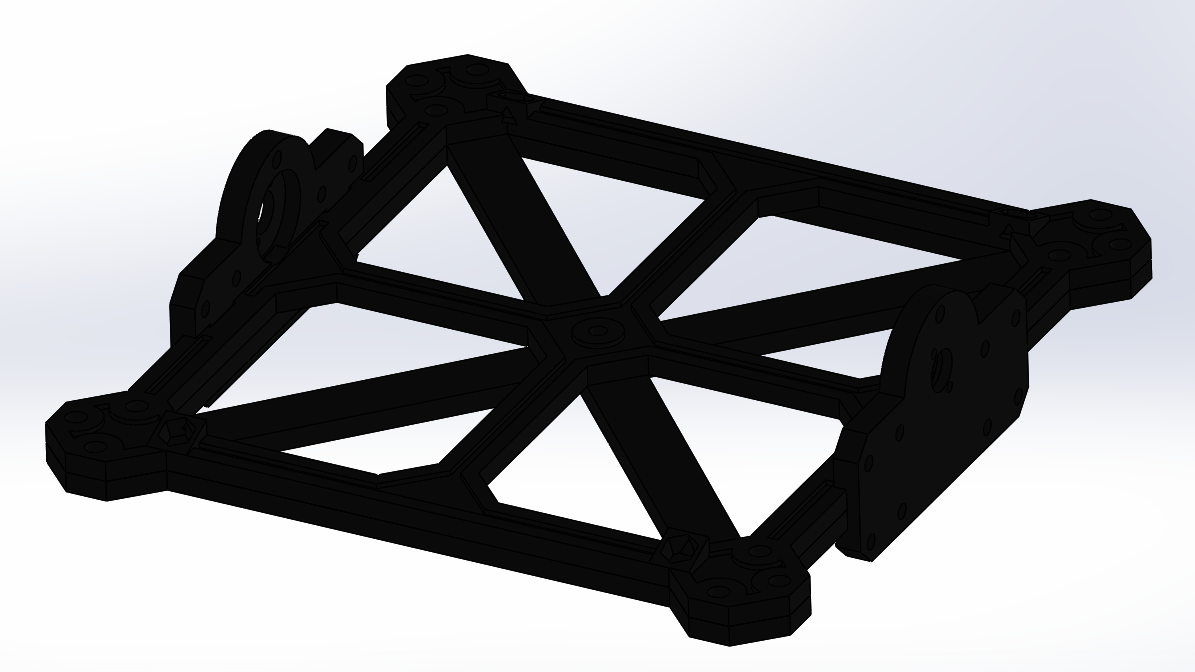
The motor mount plates align via the notches and are held in place with 8 screws. The motor mount plates were designed to fit the motors, which are secured with two M2 socket head screws.
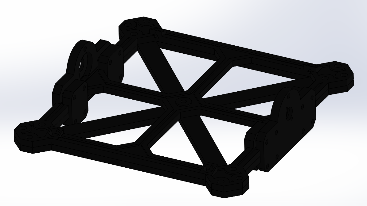
Four clamping plates are used to hold the motor mount plates in place.
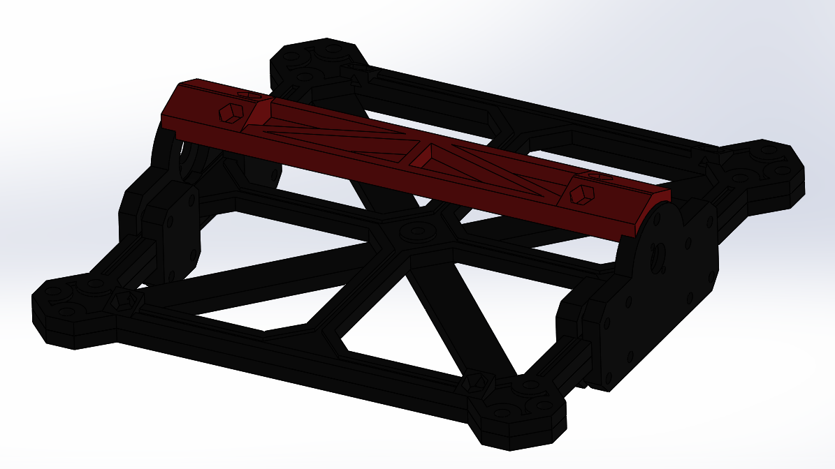
A support beam is used between the motor mount plates to provide increased stiffness and mounting points for the support places. Eventually hex nuts would be placed in the recesses and glued in place using cyanoacrylate.
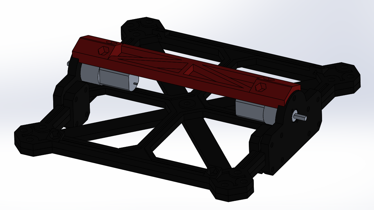
The motors are mounted during this stage of assembly.
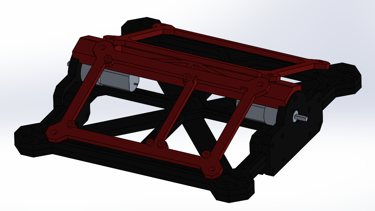
The two support plates are secured to the integrated mounting points in the chassis. The plates are setup to mount the electronics and battery. Unlike the legs, I went straight to production version fabrication right after verifying some design details. The results were quite good.
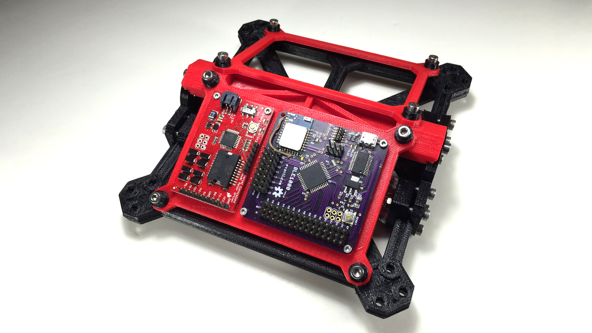
It's going to take a while to fabricate and assemble all the components. Next step, integration.