You can find the latest version of the discussed software on GitHub
The software for JanBot MK 1 consists of three parts. The first if the firmware on the Sparkfun Serial Controller Motor Driver. The second is the firmware on the BLE1000. And last, is the Android app that provided a GUI for interaction.
The Sparkfun Serial Controller Motor Driver is actually a really convenient board. It couples an ATMEGA328P with a L298 Dual Full-Bridge Motor Driver from ST Micro. Each channel of the motor driver is capable of providing 2 amps of current from 5 to 16 volts. The standard firmware on the board uses a simple set of serial commands to control each channel.
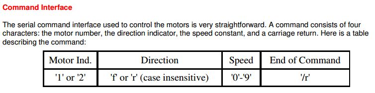
The provided control interface is rather limiting in the available control resolution. Only 10 positions are allowed in each direction. Looking at the stock firmware's code, the PWM signal is generate using the timer peripherals.
void set_speed(char motor, char speed)
{
	if(motor=='1')
	{
		if(speed=='9')OCR1A = 0x3FF;
		else OCR1A = SPEED_UNIT*(speed-48);
	}
	else
	{
		if(speed=='9')OCR1B = 0x3FF;
		else OCR1B = SPEED_UNIT*(speed-48);
	}
}
The code scales the characters 0-9 to a value between 0 and 1023. This value is used to set the output compare register, which determines the PWM signals duty cycle.
After porting the stock code to Atmel Studio, I modified the code to accept a new style of command input that would provide higher resolution control. I opted to trade human readability for data compactness with the new command architecture. The new command would be a 8 bit char, either 0 or 1, to determine the channel, followed by a single 8 bit value, which determines direction and speed. In the new scheme, the neutral position would be a value of 127, with 255 being full forward, and 0 being full reverse.
Testing indicated that everything was working as expected with the motor driver. The full source code is provided at my forked GitHub repo.
The firmware for the BLE1000, is written in the Arduino IDE. The BLE1000 acts as the main controller for the JanBot. The BLE1000 is essentially a ATMEGA644PA coupled with a BlueGiga BLE112 Bluetooth module. The source code is based on the code provided by Jeff Rowberg and his BLE112 Breakout Board. The BLE1000 is configured as a Bluetooth Low Energy device with a GATT profile that provides serial RX/TX characteristics.
The BLE1000 receives joystick input updates via Bluetooth, performs single joystick to tank drive mixing, and communicates the results to the motor driver. In addition to this, it also controls a couple WS2812 LEDs, also know as NeoPixels from Adafruit.
The attribute value events sent from the GUI take the form of 3 bytes of data. The first byte is the X axis, the second byte is the Y axis, and the third byte is used for miscellaneous flags. The joystick axis values are fed to a mixer which produces commands for the motor driver. The full source code is provided at GitHub.
The final part of the software stack is the GUI. The GUI takes the form of an Android app that communicates over BLE to the BLE1000. Mobile development being my bread and butter, this portion was quite easy. The interface consists of a screen to pair the devices, and a screen with a touch joystick and some label for status readings.
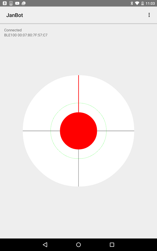
If you're curious about the app, please take a look at the source provided at GitHub.
Since the basic software to drive this thing around is done, I'll be doing some analysis on performance and determining next steps for improvements.