I was lucky to be one of the early few that received the HTC Vive on launch day. Its been a great experience and I feel the future looks bright for VR. One of the slightly awkward aspect of gaming on the Vive is trying to shoulder a VR weapon. A few interesting examples of rifle controllers for the Vive have popped up on the Vive subreddit and on Thingiverse. They were a bit lacking in adaptability for the various titles that have shouldered weapons. Therefore, my goal for this project is to build a Vive controller accessory that is adaptable to most games. Three separate adjustment points are needed to ensure proper alignment and comfort, length of pull, cheek weld height, and controller angle.
The first step is to figure out how to couple the Vive controller to the accessory. HTC hasn't released any detailed CAD drawings or model to the public yet, so I used the 3D models provided with SteamVR. The models have a lot of little detailed that aren't critical dimensions. The model was simplified by removed the extra details to make working with the general form much easier. The model was then exported from 3D modeling software as an STL ready for import into the CAD software.
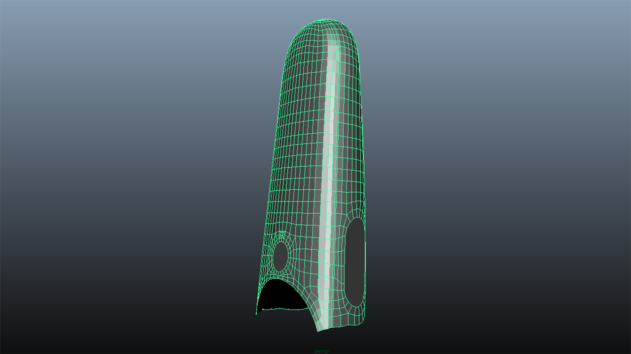
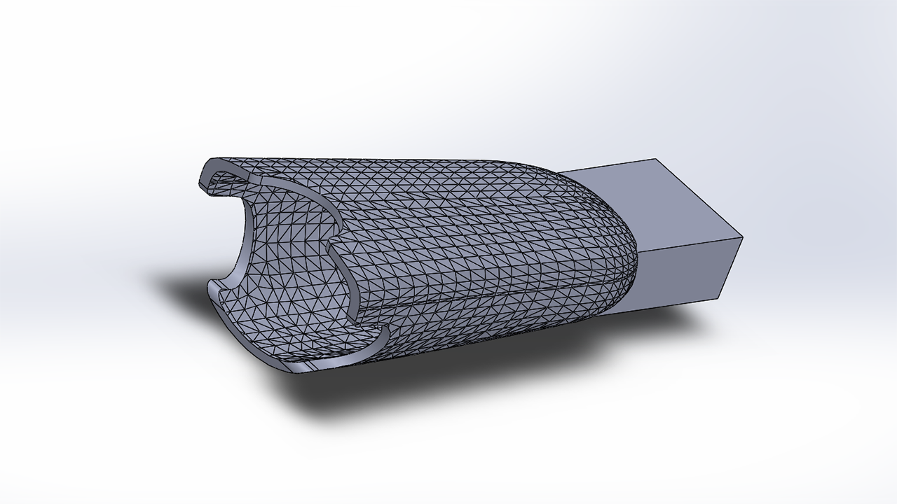
The STL was then imported into CAD software. I trimmed the part to a flat face roughly halfway up the grip buttons. After that, two versions of the part were created, one scaled to 104% and another to 115%. The 104% part will be aligned and subtracted from the 115% part. This will create a part that allows a Vive controller to comfortably slot in, and conforms to the general shape of the controller. Holes were cut out for the grip and system button, as well as a hole for the wrist strap to pull through. I add some flat areas to help with test fitting and alignment, so they are not the finalized geometry.
The part was exported and sliced for 3D printing. The goal of this print was mainly to gauge the fit and ergonomics of the design.
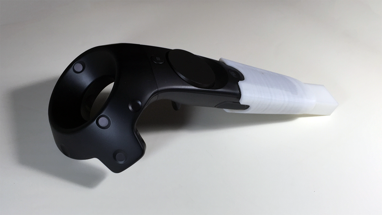
The part was printed in ABS on a Zortrax M200 with 0.14mm layer height. Print time was about 4.5 hours. The fit against the Vive controller was excellent, leaving just enough clearance to account for a coating. The grip was comfortable and the button were still easily accessed.
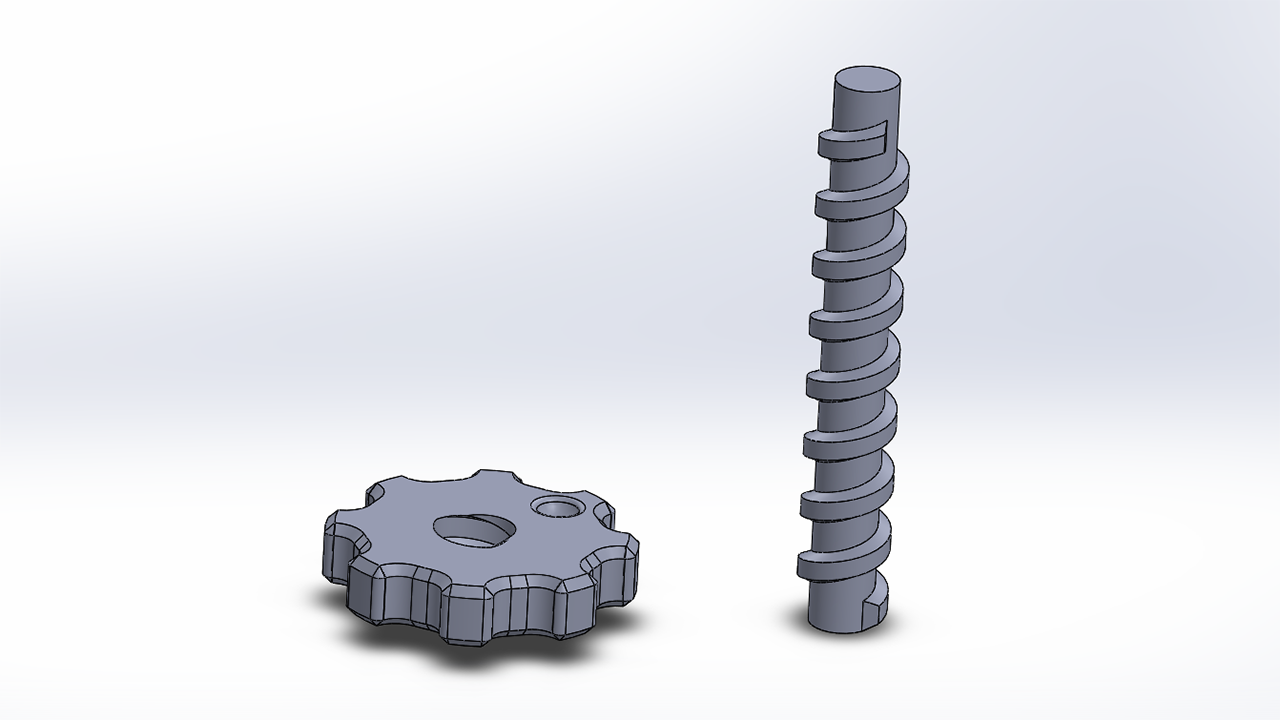
While the part was printing, I worked on a prototype for the lead screw mechanism that would be used in the 3 adjustment points. The lead screw has a pitch of 10mm with a 12mm diameter. The knob has 0.3mm of tolerance in the screw profile to reduce the chance of binding. The knob also has a detent point for testing the detent shape.
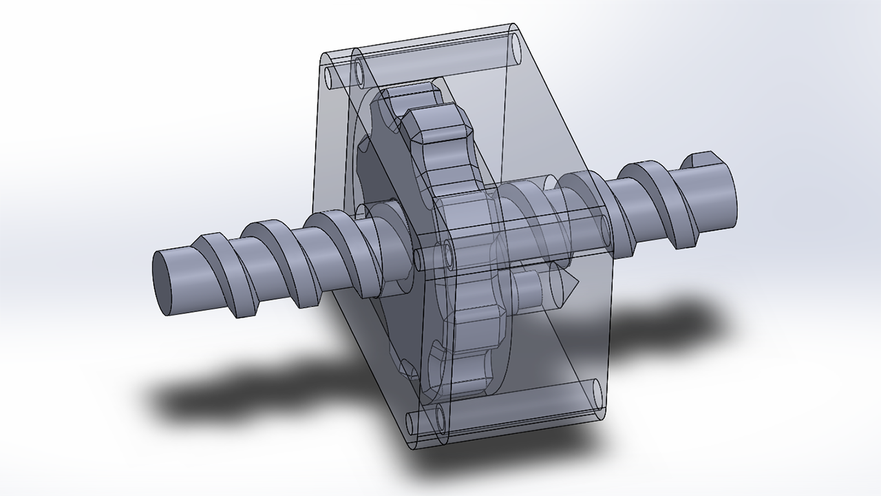
This is the testing rig I'm using to validate the tolerances on the eventual 3d printed parts. A 9/32"x1/2" compression spring sits behind the detent and provide the spring force. I'm also using #6-32 threaded brass heat-set inserts along with matching #6-32 socket cap screws to hold it all together.
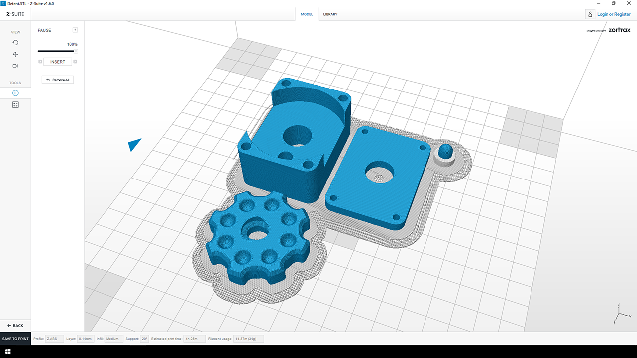
A minor tangent on 3D printing. The Zortrax M200 and the Z-Suite software, produce excellent prints without much tinkering. Of all the printers I've used and owned, the Zortrax has been by far the best consumer 3D printer. Great surface finish quality and dimensional accuracy. Back to the engineering.
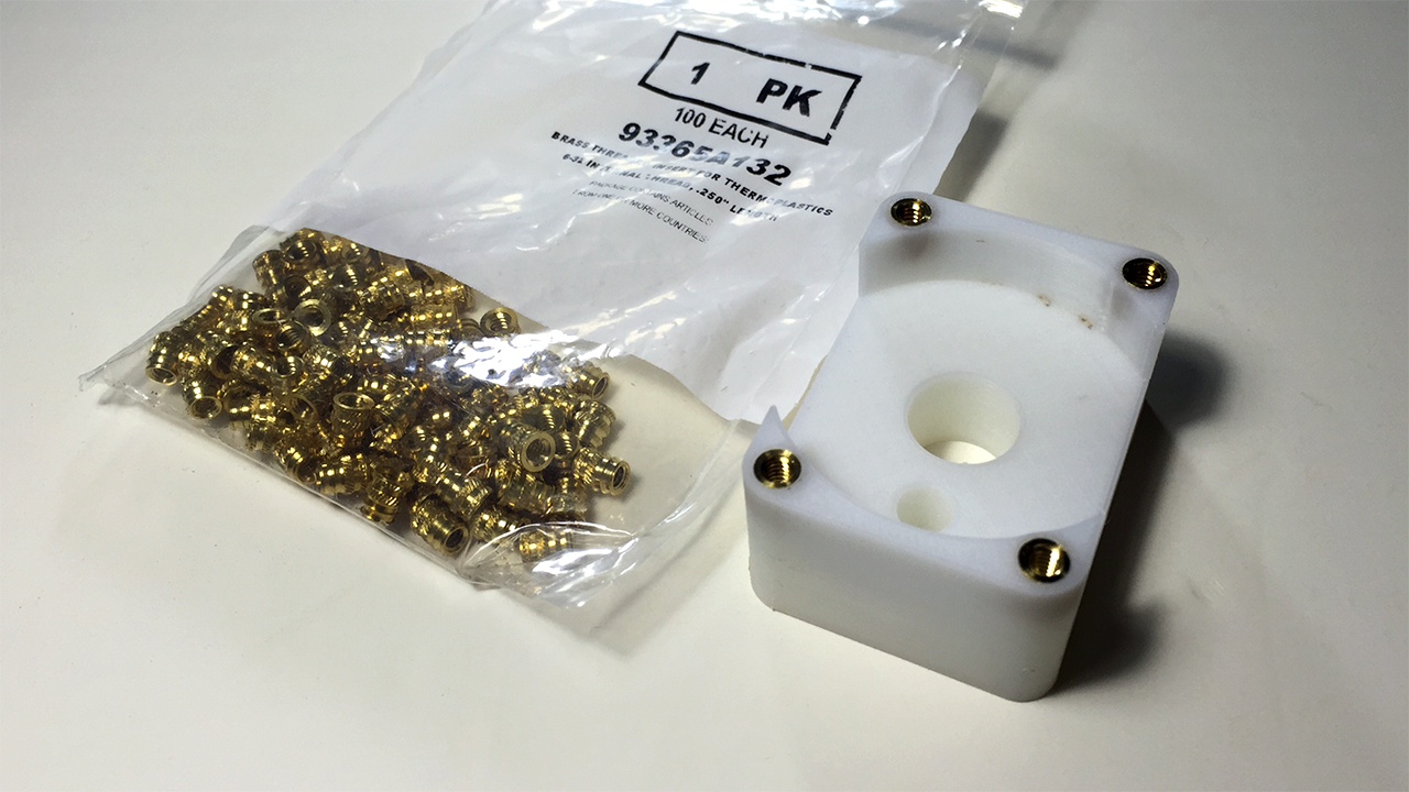
Heat-set inserts are great for 3D printed parts, they add strong threads that are capable of carrying load. They are put in place with a soldering iron and a specialized tip. Once the insert is pushed in, its really not going to come back out. It's a better choice than trying to rely on 3D printed threads.
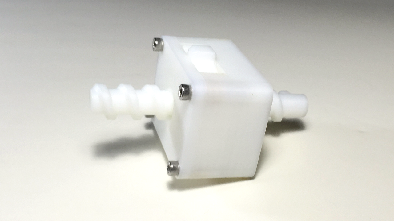
The realized parts assembled. Works as designed, with a satisfying clicking sound when turning the knob and actuating the detent.
I'll be going over the stock and mechanism design in the next part of this series.